Table of Contents
In the previous article I built a wireless car, with Lego servo and Lego motor, powered by a Lego power pack. The code, both the embedded one and the backend one, was in Rust.
Now, I'll make it FPV with an arducam, still controlled in Rust, and still Lego powered.
If you're here to learn, I suggest you really start by reading the previous article.
Features
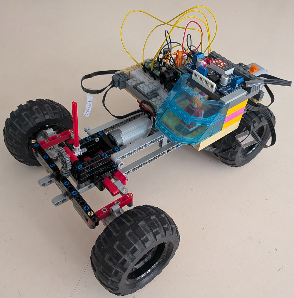
This is the FPV Picomobile:
- real-time video feed from the embedded cam (7 to 8 FPS in 640x480)
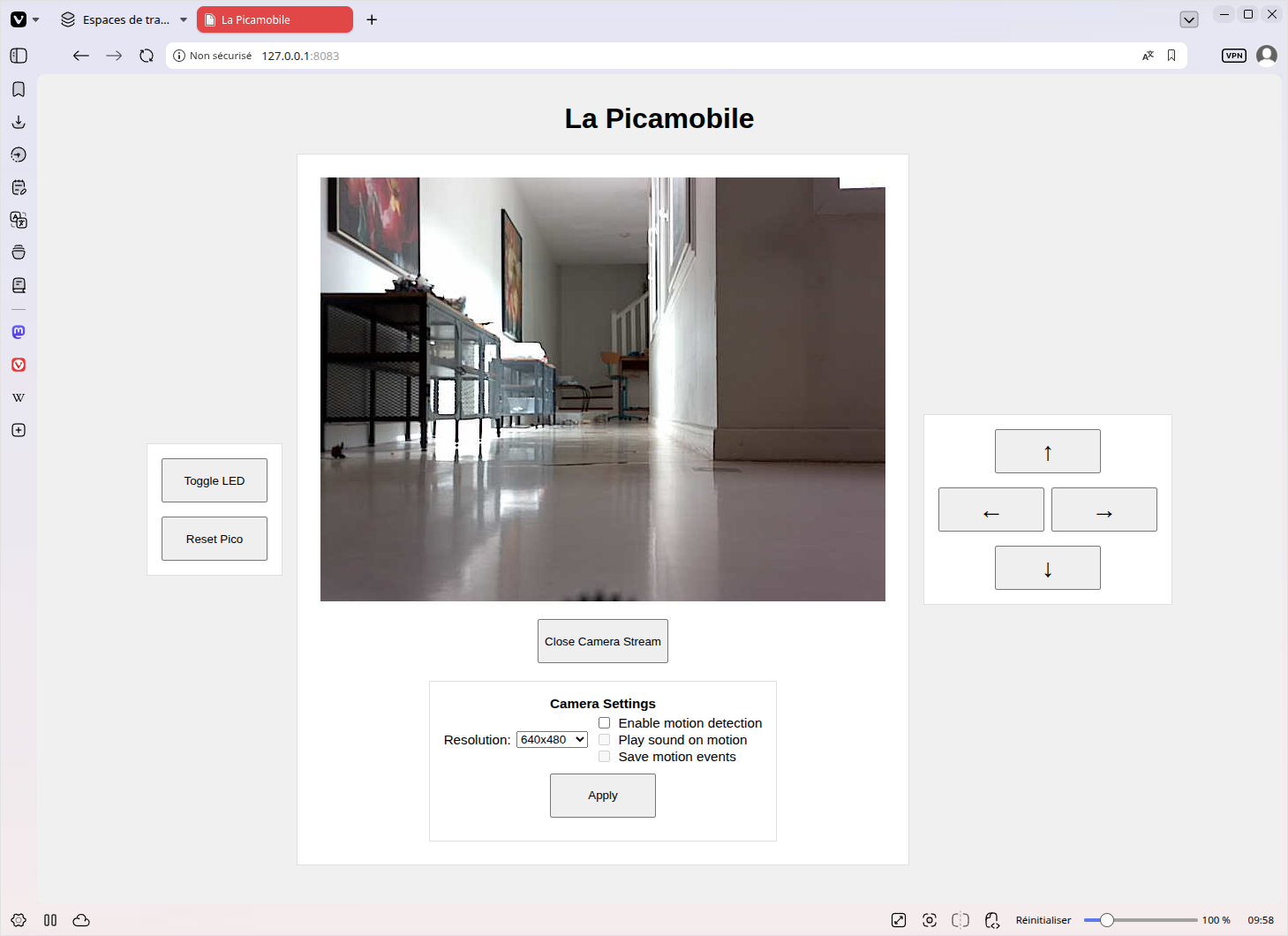
- arrow keys in the Web GUI control the car, as you'd do in any game
- 100% of the power comes from the Lego power pack (holding 6 AA 1.5V batteries)
- standard Lego servo
- standard Lego motor
no_stdembedded Rust with multiple async tasks running in parallel to receive commands, drive the car, control the camera, send the image stream, and more- Rust backend communicating with the car in TCP over Wi-Fi and with the browser in HTTP
- no separate probe: debugging and installation are done with the USB cable
- rodent motion detector (yes, seriously)
Here's what the control GUI looks like:
Hardware parts
All the parts of the previous Picomobile
See here for the Raspberry Pico WH, the Kitronik 5331, small components, and the Lego parts. You'll also see how to cut flat Lego cables.
Smaller breadboard
With a lot of experience in software and almost none in hardware, my initial strategy was to wire the components onto a large breadboard, with a lot of room, and additional jumps to ease refactoring.
Electronics, and especially high-frequency buses such as SPI, really don't like that.
Long wires inside the breadboard behave like tiny antennas and capacitors.
The builds (four of them) I made on large breadboards were very unreliable, driving wasn't possible without crashing, the arducam usually wasn't even responding.
Prototypes I made on small breadboards with as short as possible communication cables have SPI and I2C perfectly working.
So, rather than enduring what I did, start with a small breadboard and short cables. And don't make power paths bigger than necessary, don't use the second power rail to avoid introducing parasitic capacitance or ground loops.
Arducam
I went with the Mini module Camera Arducam Shield OV2640 2MP Plus, which is high resolution, fast enough, can be controlled by I2C (which the Pico has) and can send JPEG-encoded images on a SPI bus (which the Pico has).
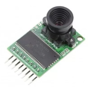
That's by far the most expensive part, costing about 30€.
Buck Converter
Writing the software was surprisingly almost straightforward.
Electronics... Not so much.
The biggest challenge, after the inductive coupling and capacitor ones I mentioned in the breadboard chapter, was powering everything, that is the Pico, the Arducam, the Servo, the motor, from the Lego power pack.
Actually, this is the reason I had to build half a dozen different circuits on the small breadboard before finding one which works well. In most of them the power was lacking which made parts, most often the servo, very unreliable.
The Kitronik 5331 is able to provide about 100mA at 3.3V.
It's enough to power the Pico and, with a capacitor added, support the short spikes which are assumed to be at 200mA due to the Wi-Fi (according to the official documentation, which states that "due to the additional current draw of a Pico W's wireless features it is not recommended to use the wireless functionality with this board" this shouldn't be OK, but in my experience there's no problem).
But it proved not enough to also power the Arducam, which itself asks for about 150mA.
I tried first with linear converters, that is components which basically convert the excess voltage into heat, but that didn't work well.
What works is to use a buck converter: those converters waste almost no power.
Take one which can convert from 9V to 5V. They usually have a LED screen to display both the input and the output voltage.
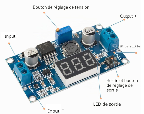
Such converter costs about 3€.
Schottky diode
Sometimes you'll have to plug the USB cable, for example to deploy a new version of the embedded software.
Doing it with no protection of the buck converter would probably fry it.
A Schottky diode, which costs a few cents protects the buck converter from being backfed by the USB's 5V power (VBUS).
I took a 1N5819, which has a low voltage drop (~0.3V to 0.5V) and handles up to 1A of current.
The software
You can fetch it at https://github.com/Canop/picomobile
It's the software for the previous picomobile, for this one, and for the intermediate steps. It works for all.
The repository contains 2 programs:
picomobile-embedded, which runs on the Picopicomobile-gui, which runs on a PC, serving the web based GUI and communicating with the Pico through Wi-Fi
Both programs are very similar.
They're both in async Rust.
They're both servers, running tasks in parallel, accepting connections, receiving, interpreting; and executing orders, tunneling images.
On both programs, parallel tasks communicate with channels.
The backend runs on tokio + axum.
The embedded application runs in no_std on Embassy.
Their code really looks the same even if one is no_std and runs on a tiny chip with no OS and not even enough memory to keep an image.
Here's how they compose and communicate:
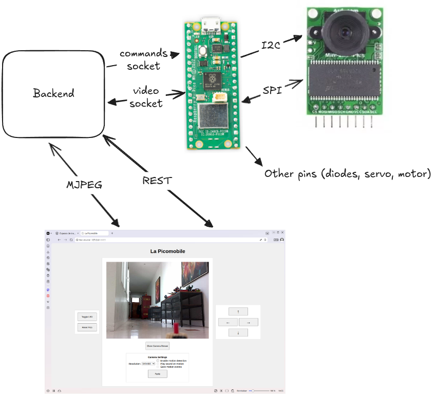
The Pico listens on 2 different ports: one for commands, and one for images.
Embedded code
You'll find it in picomobile-embedded.
It's the code which, when compiled, runs in the RP2040 chip of the Pico.
The main loop (main.rs) listens for sockets and, on an open command socket, parses commands, and acts accordingly:
- a LED toggle command is directly handled, that's just a pin to set to either low or high
- a driving command is sent to a channel for the driving task
- a Quit command
Besides the main, the embedded code runs the following parallel tasks on Embassy:
- The driving task (in main.rs too). Having it out of the main loop allows it to manage timeouts, ensuring that when there's no stop command received the car stops. This prevents crashing on network losses
- The
camera_streaming_taskfirst tries to initialize the arducam. If that was successful, then it listens for connection on its own port, and on each connection, configures the arducam's resolution then, in a loop, asks the arducam for an image and sends to the socket the bytes as they arrive from the camera (an image doesn't fit in the tiny memory of the Pico) - Technical stacks that allow the network and USB logger components to run include the
net_task, thecyw43_task, and thelogger_taskdefined in main.rs.
The arducam related code has a lot of delicate parts. There was a lot of trial and errors in the making, but it seems reliable.
In practice I guess the problems you'll encounter with the camera will rather taste of electronics: too long wires, electromagnetic interference in adjacent wires, transient current spikes, etc.
This task-based architecture, with each task managing its state, makes it easy for the embedded code to adapt to the plugged hardware. That's why the same software can be kept without change when the electronics wiring is changed.
Backend/GUI code
You'll find it in picomobile-gui.
Its purpose is to serve the web GUI and tunnelling commands and video streams between the browser and the Pico.
There's also a feature that you probably didn't expect: a motion detector, making it possible for the same software to watch for, eg, rodents suspected to visit your house.
Serving the static files and answering to REST are done in quite standard Axum ways.
Command tunneling is done by the tunnel_commands_task which runs asynchronously, receiving commands from the REST handler in a mpsc channel.
The image flow is a little more complex because there are several consumers:
- (potentially) several web pages
- a motion detector
Thanks to tokio's broadcast, it's quite easy to orchestrate.
The image "producer" holds a broadcast Sender. When there are Receiver listening, it queries the Pico to get back a stream of images. It then just broadcast the images to the receivers, not concerning itself with their flows and delays.
The application is organized around those channels whose initialization is visible in main:
- the command channel: Sender is the REST endpoint handler, Receiver is the
tunnel_commands_task - the video broadcast channel
- a channel for motion detection events: Sender is the
move_detector_task, receiver is an event saver task - a broadcast channel for the camera configuration: most tasks listen to new configuration so that they can change their behavior when a REST endpoint handler broadcasts a new one on user request
Such architecture makes it very easy to plug new tasks, or to adapt to ones being off at a time
Step by Step
Here's the finished product. Or rather my version.
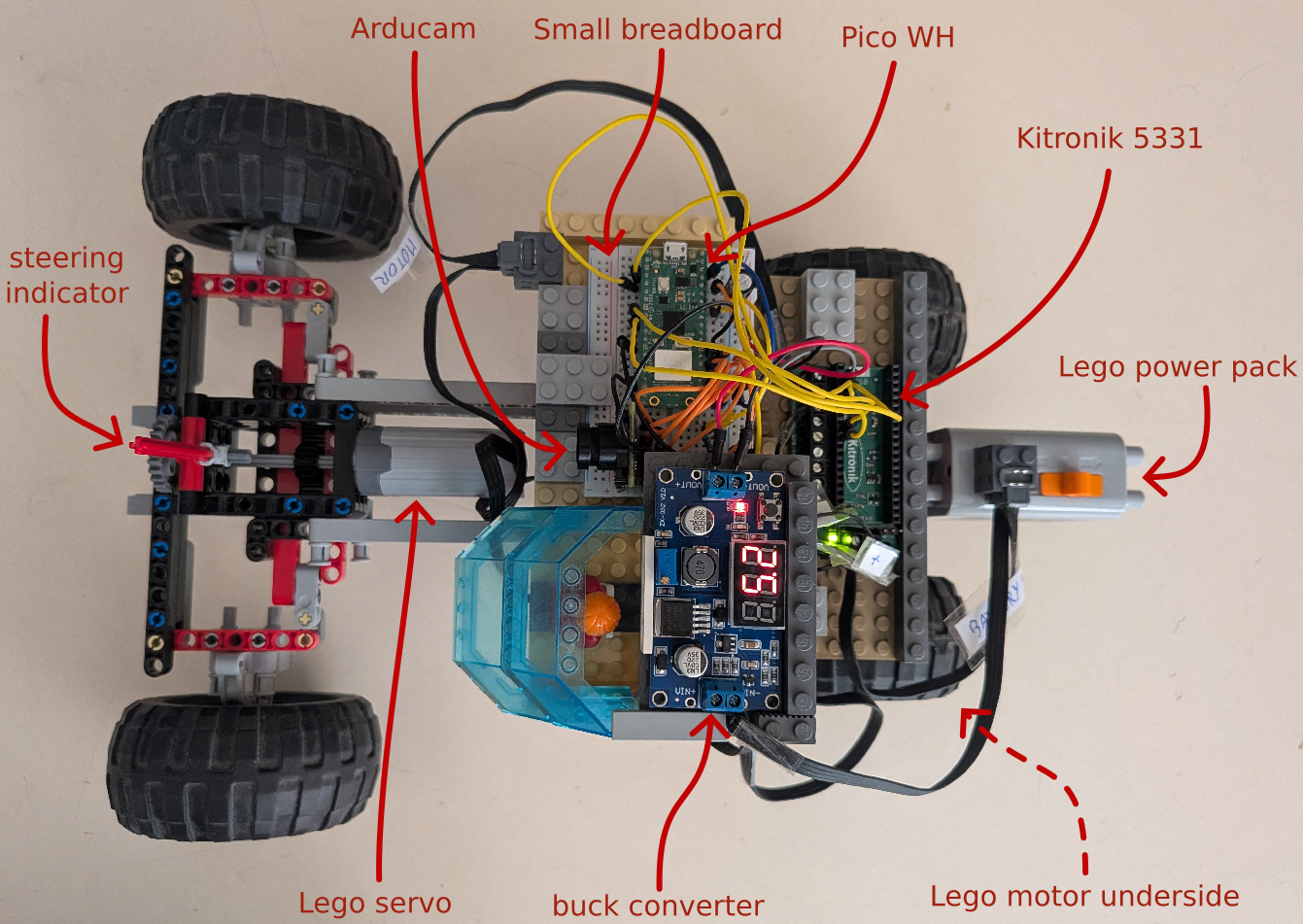
But we'll do it step by step, so that each one can be checked.
Just an LED
This circuit is very simple but lets you already check
- the build chain
- USB logging
- Wifi connecting
- Backend connecting to the Pico over Wi-Fi
- Command pipeline from the browser to the backend to the Pico
You'll need a reference for the Pico pins. Here's one: https://picow.pinout.xyz/
Plug the Pico on the breadboard.
Add a resistor in series to a diode, longer leg (anode) first, from GP27 to a GND. You may use a few jumper wire. In my setting, I used the - (blue) rail of the breadboard to go back to the Pico's GND.
Then plug the USB cable in the Pico. If you may have already a program on the Pico, press the Pico's button before plugging it, and release after it's plugged. This resets it to USB mode.
It should look like this:
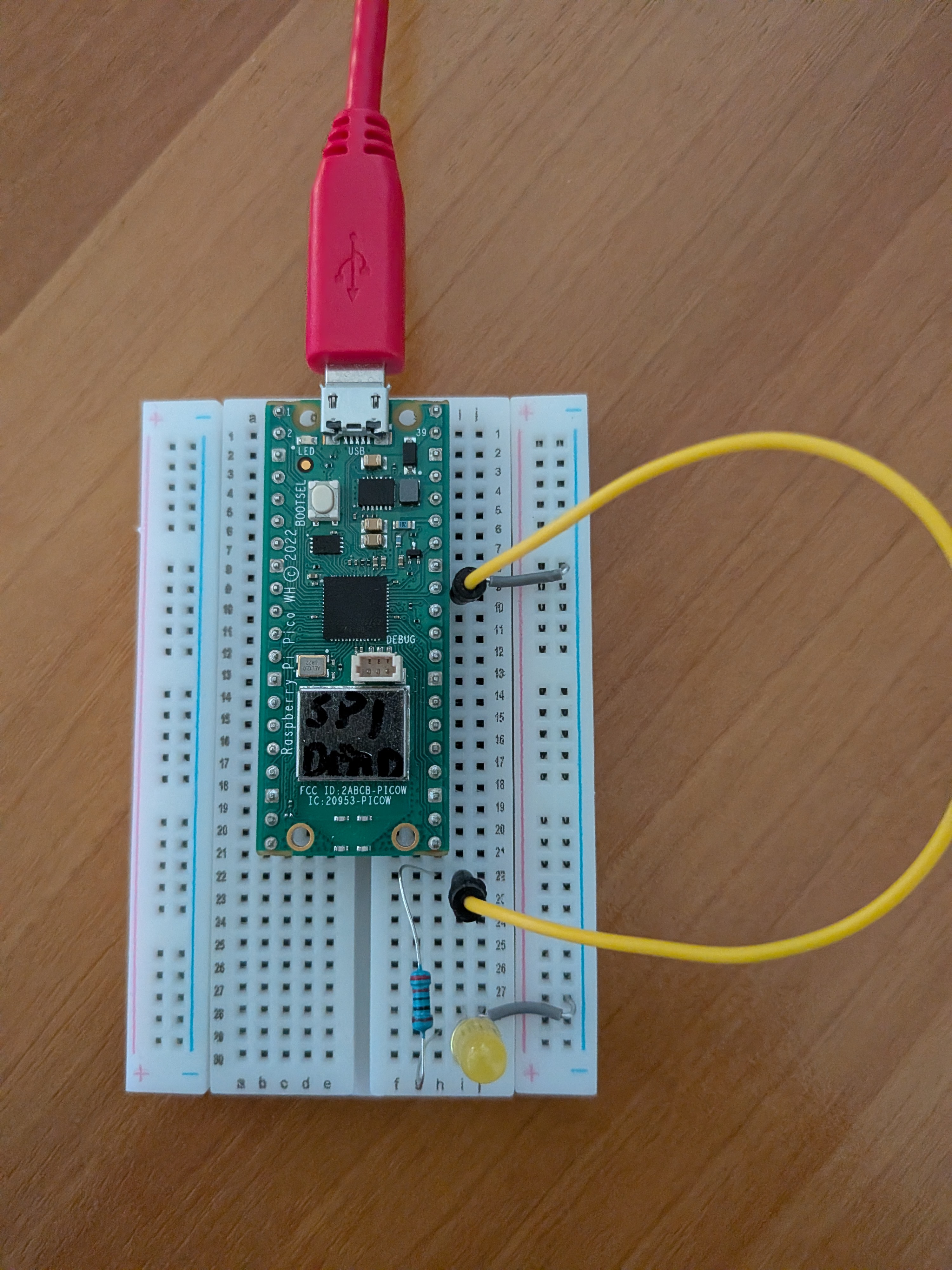
(except you probably don't have a "SPI dead" Pico as a result of a previous experiment which also burnt your finger)
Assuming you installed the necessary dependencies listed in the previous article and fetched my picomobile repository, move to the picomobile-embedded directory.
Then run cargo run which compiles, installs, and starts the program on the Pico.
To see the log lines, connect with tio /dev/tty.usbmodem* . The log lines should appear. There's no need to stop tio when you stop or unplug the Pico but if you want to quit it, do ctrl-T Q.
The log shows you the IP address the Pico got on your local network, for example 192.168.1.25.
Now, move on to the picomobile-gui directory to start the backend (this can be on another computer).
Launch it with eg cargo run -- --car-ip 192.168.1.25 then open in your browser the web page from the URL the backend prints.
At this point, only 2 buttons are useful:
- the
Toggle LEDbutton. Try it to check it works - the
Reset Picobutton, which you'll use when you want to install a new version of the embedded software
If everything works, you're ready to go to the next chapter.
Video stream & Rodent detector
Before any change of the circuit, unplug the USB cable.
Without removing the resistor and diode, you'll now plug the Arducam onto the breadboard (there's very little choice for location if you have a small breadboard) and wire it to the Pico.
| Arducam (left to right) | Pico | Purpose |
|---|---|---|
| CS | GP17 (SPIO CSn) | SPI chip select |
| MOSI | GP19 (SPIO TX) | SPI Data - master output slave input |
| MISO | GP16 (SPIO RX) | SPI Data - master input slave output |
| SCK (SCLK) | GP18 (SPIO SCK) | SPI clock |
| GND | GND | power ground |
| VCC | 3V3 out | powers the Arducam |
| SDA | GP20 (I2C0 SDA) | configuration |
| SCL | GP21 (I2C0 SCL) | I2C clock |
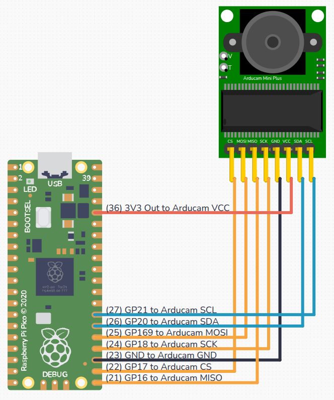
Plug the Pico to your computer again so that you can read the log.
The log will tell you whether the Arducam initialization was successful. If it isn't, there's very probably a problem with your wiring. Check it.
Be careful that wires must be as short as possible. Sometimes electromagnetic interference problems can be solved by separating the SPI wires a little.
When the Arducam is successfully initialized, go check the Web GUI: we'll now use the middle panel. Click Open Camera Stream.
You should get a display like this:
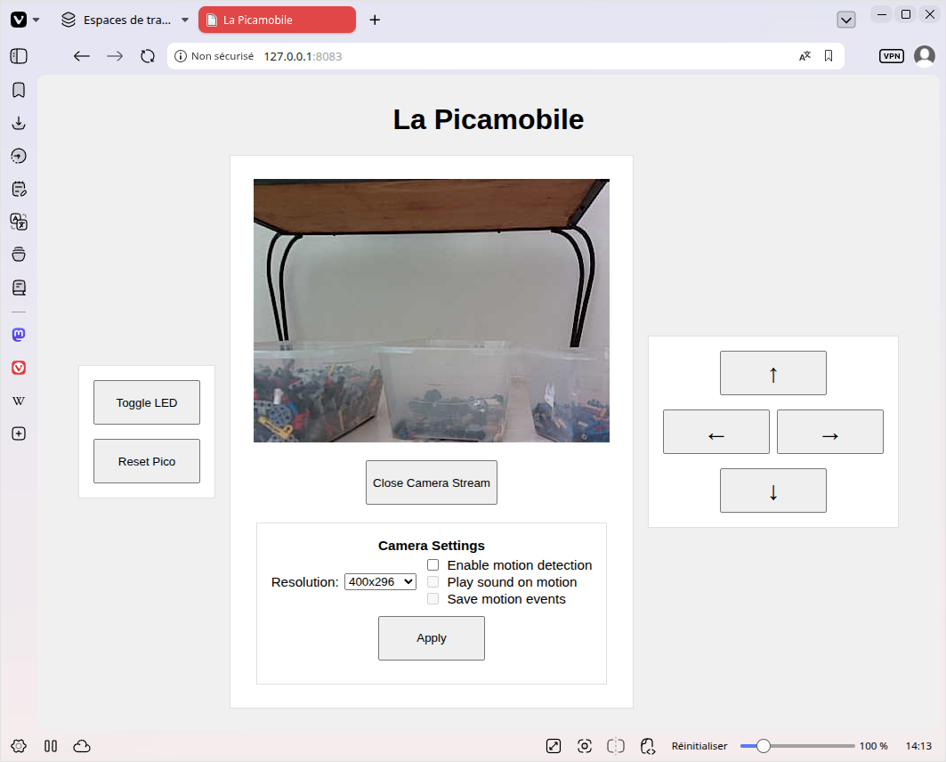
You can try changing the resolution, or enabling motion detection (both the sound and the image saving are done in the backend, not in the browser).
If you're interested in motion detection, you can try tuning move_detector.rs. I'll consider it off-topic for the present article.
You don't have to keep the Pico conntected to your PC, that wouldn't be convenient. You can power it from a simple USB-C charger.
Lego Power
Now, the goal is to use the power of the Lego power pack.
Start by unplugging the Pico from the USB.
We first need to make a power cable. Or 2, because we'll need the second one in the next chapter.
Flat Lego Power Function cables contain 4 wires and have 2 identical heads, like this:
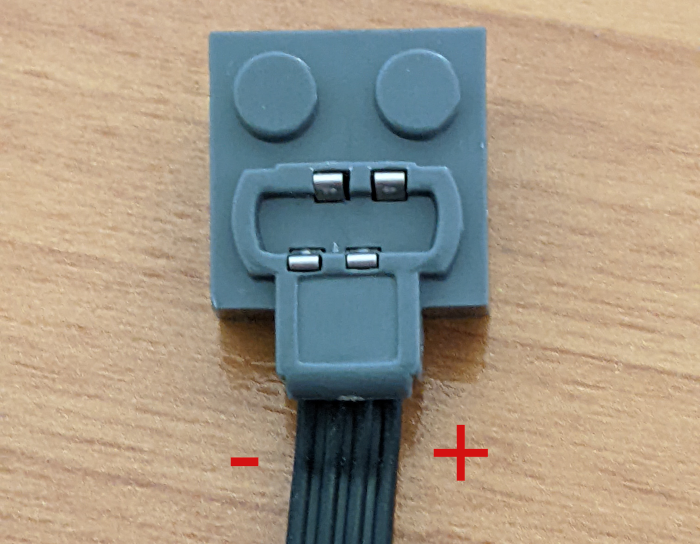
(note the + side)
Cut a Lego cable in the middle, and separate then strip, over a cm, the external wires.
Connect those wires in the Input - and Input + pins of the buck converter, with polarities matching the one on the picture above.
Plug the flat head on the Lego power bank, and set it to on. The buck converter should light, and should display a measure in volt. Use the display select button to display the output voltage. Then turn the screw until the output is somewhere between 5.0 and 5.2V (0.2V to compensate for the Schottky diode). Checking with a multimeter is a good idea.
Turn the Lego power pack off, then plug the outputs of the converter to the power rails of the breadboard (the ones nearest of the "VSYS 5V" pin of the Pico).
Plug a Schottky diode (probably 1N5819) between the "VSYS 5V" pin of the Pico and the + rail of the breadboard. The white stripe of the diode MUST be on the Pico side.
Add a jumper wire between a GND pin of the Pico and the - rail of the breadboard.
Plug 2 capacitors of different size (eg 1 and 100 μF) between the two power rails.
Check everything (it should make sense), then re-check, and put the Lego power pack on ON.
The Pico should start and work as before, serving the images on request.
Motor and servo
As we'll add a Kitronik, and more cables, it's a good idea right now to build a board with Lego so that all the components stay together. Later on, you'll put this board on the car.
We need a Lego power cable, identical to the one we made in the previous chapter.
We also need a more complex cable that utilizes all four internal wires.
Take half a flat cable. We now need the four wires, and to have them well separated. This is a delicate operation, I had to put some adhesive tape to protect where I had cut the protection.
You should probably do as I did: label the + and - wires so that you don't plug them wrong.
The + and - go to the power + and - of the kitronik.
The 2 internal wires must be plugged into the Motor2 pins of the Kitronik (order doesn't matter).
In the previous car, the Pico was plugged in the Kitronik, but in this one, the Pico stays on the breadboard, which frees the pins we need to communicate with the Arducam. We still need to connect some pins for control of the servo and motor: add jumper cables between the GP2, GP3, GP6, GP7, and GND pins of the Pico to the same pins (same location) of the Kitronik.
Make sure both flat power cables are plugged onto the Lego power bank, then set it to ON.
When using the web GUI, the 4 arrow buttons should control the servo and motor.
Lego car
Now, just build a Lego car with the piece that already work.
You'll turn it ON and OFF a lot of times, so make sure the Lego power pack toggle is easy to reach.
You should use a standard differential so that the car can turn and move at the same time without effort.
Pay special attention to the direction.
I replaced the one of the previous car because you really need an efficient one. The power is scarce in our build and you don't want the servo to pump it more than needed.
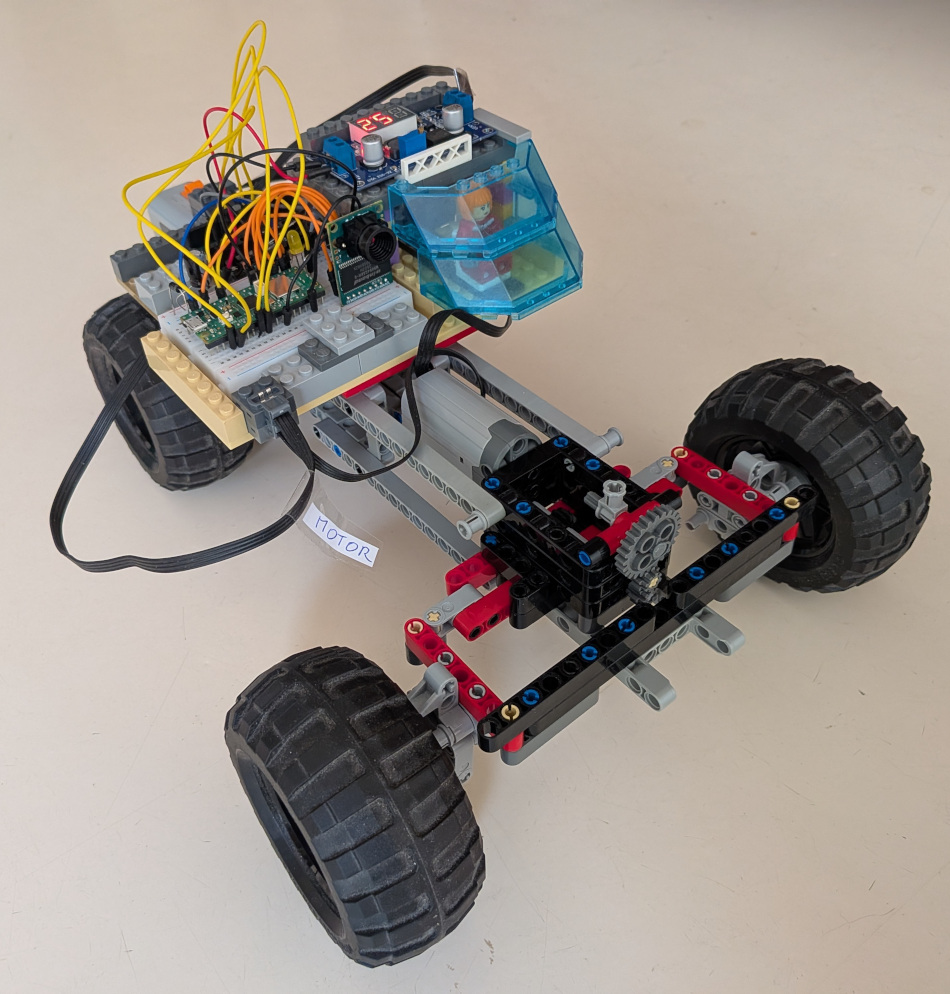
Here's the steering mechanism I settled to:
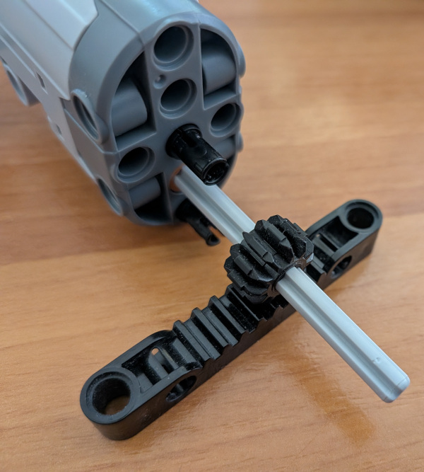
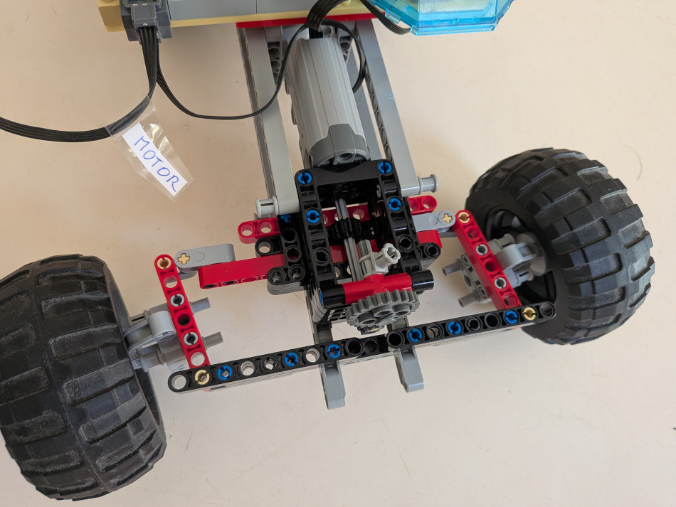
You may have noticed a steering indicator. It's useful if you have to deal with power problems, so that you can check the car turns as requested without leaving your computer. If you add one, don't forget that the number of gears must be odd if you want the indicator to be exactly vertical when the car isn't turning.
Make sure everything is securely fastened, then go on.
The video stream runs at a little more than 7 FPS, that's not much, you'll have to be careful, it's not as smooth as in video games.
Conclusion
My limited experience in the embedded world doesn't allow me to speak with absolute authority, but inferring from my background in backend software, I am convinced Rust is uniquely powerful for building fast and reliable embedded systems.
Managing parallel tasks—like handling driving timeouts to prevent crashes during network loss while simultaneously streaming a video feed—usually requires a complex RTOS or invites subtle concurrency bugs. Embassy’s async framework brings the benefits of multitasking to no_std environments with a minimal memory footprint.
Because Rust checks ownership and thread safety at compile time, the "fearlessness" translates directly from software to hardware: you can stream images byte-by-byte without buffering or risking memory corruption. The embedded Rust ecosystem is maturing rapidly, proving that you don't need a heavy operating system to build safe, concurrent, and resilient machines.